ArnavA_BSE_Portfolio
Walkthrough of me creating an Arduino tic tac toe matrix.
Project maintained by Arnav-Aa Hosted on GitHub Pages — Theme by mattgraham
Arduino Tic Tac Toe
I am working on an arduino tic tac toe matrix.
| Engineer | School | Area of Interest | Grade |
|---|---|---|---|
| Arnav Ashok | Santa Clara High School | Electrical Engineering | Incoming Sophomore |
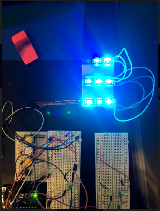
Final Milestone
My final milestone was changing the button interface and expanding into a 3x3 matrix. I would use one button to scroll through the LEDS and another to select the LED. I also used ledstrips instead of the previous leds. This made it so I could give different rgb values to each led on the ledstrip. I used the colors green and blue on the LED strip to correspond to the X and O on tic tac toe. To create the 3x3 matrix, I cut three pieces of led strip, each consisting of 3 leds each. I soldered these strips together the create the 3x3 matrix, completing the tic tac toe board.
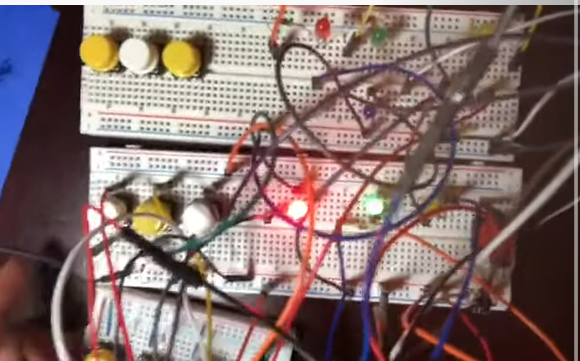
Second Milestone
My second milestone was working on a winning formation and expanding the tic tac toe matrix. I added a new row of 3 more buttons and changed them from the previous ones for aesthetic purposes. This row of buttons would correspond to the next row of lights in the matrix.I had coded the arduino to identify the 8 win conditions of tic tac toe and having a win formation to go with it. The winning formation would consist of buzzer sound effects and lights. The lights would highlight the win condition by blinking for a couple seconds followed by sound effects played by the buzzer.
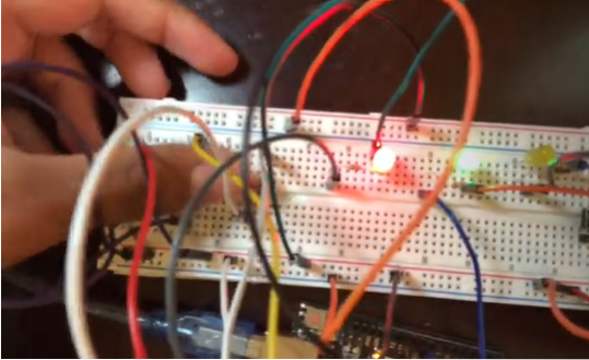
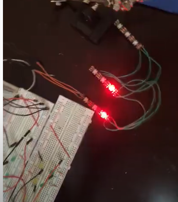
First Milestone
My first milestone was getting the arduino board and software set up, and then creating a smaller scale of the tic tac toe board. I had started with a 3x1 matrix at first, to serve as a prototype but also having room for expansion. Each light could be set to a binary set of blue and red colors. This would correspond to the “x” and “o” on a standard tic tac toe board. I had also added a restart button which would turn each LED off when pressed, as a way to start a new game.